Update (January 2024): I’ve written a second post on this subject that goes into greater detail and includes datasheets, example COMSOL files, and more. If you have questions after reading this post, please read the deep dive!
I’ve wanted to model magnetic particle motion in COMSOL for a while. I’ve heard great things about the software, so I wanted to try it for our microfluidic chip designs and magnetics problems. More and more of my lab coworkers seem to be using nanoparticles, so I also wanted to look into user-friendly simulation tools. Before our lab had access to COMSOL, I would often write my own simulations in Python or export results from specialized tools, like Finite Element Method Magnetics (FEMM) and use a makefile to glue the final simulation together. This approach works for me, but it’s different for every project and downright hostile to my collaborators.
I expected a steep learning curve, but I actually found COMSOL to be intuitive and even enjoyable. COMSOL even has a particle tracing module that simplifies particle interactions with fluids. Unfortunately, the default interface only supports charged particles with no magnetization. Our particles have no charge, at least theoretically, but they do have a magnetic moment in the presence of an applied magnetic field. In COMSOL things usually just work, but we need to do some customization if we want to use this feature.
Model Definition
The particle tracing module allows us to specify a general force to apply to each particle, which we can use to implement our magnetic force. The conventional expression for the force (N) on a superparamagnetic particle is:
\[\mathbf{F} = \frac{V \Delta \mathcal{X}_v}{\mu_0} (\mathbf{B} \cdot \nabla)\mathbf{B}\]Vectors are in boldface, \(\mathbf{B}\) is the magnetic flux density \((T)\), \(V\) is the volume of the particle, \((m^3)\), \(\mathcal{X}_v\) is the dimensionless magnetic volume susceptibility, \(\mu_0 = 4\pi \times 10^{-7}\), and \((\mathbf{B} \cdot \nabla)\mathbf{B}\) is shorthand for the convective operator. The expression \(\Delta \mathcal{X}_v\) refers to the difference in susceptibility between the bead and the surrounding media. For non-magnetic media, it is common to approximate the susceptibility of the surrounding media as zero, which simplifies the expression.
This expression provides a good approximation to the forces on magnetic particles and is very common in the literature. An equivalent expression was used to compute trajectories for magnetic bead capture in [2], [3], and [4]. However, it should be noted that additional terms may be necessary to account for the remnant bead magnetization - particularly for very small applied fields [1]. In such settings, a more complicated force model can be more accurate.
To use this formula with COMSOL’s particle tracing module, we need to break the force into its three Cartesian coordinates. This results in a long expression with many partial derivatives, but the result is really just the Cartesian form of the convective operator multiplied by a scalar. For our COMSOL implementation, it is important to note that all nine partial spatial derivatives of the B field are needed.
Model Implementation
Our model will use the particle tracing module, AC/DC module, and PDE module. We will model a permanent N52 neodymium magnet with the magnetic-fields-no-current interface of the AC/DC module. To obtain the derivatives of the field, we will use a general form PDE. Finally, we will model the particles and the magnetic force in the particle tracing module.
Our first study will be a stationary study of the magnetic field and its spatial derivatives. Our second study will be a time-dependent study that uses these results to find the trajectory of a magnetic particle.
Generating a Magnetic Field
We have used products from K&J Magnetics and found that they provide excellent technical information, so we will use their D4X0-N52 neodymium magnet for this COMSOL model. From the datasheet, we are given a radius of 0.25 inches, a height of 1 inch, and a remnant flux density of 14,800 gauss. This information is sufficient for a simple permanent magnet model. For modeling purposes, we’ll also enclose this magnet in a 100 cm cube of air.
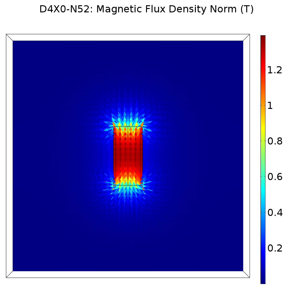
We are also given a measurement of the surface field from the manufacturer, which we can use as a sanity check for our model. Along the magnetization axis, they measured a surface field of 7343 gauss, or approximately 0.7 tesla. If we export a Cut Point 3D measurement at the surface field test location, we also measure 0.7 tesla.
 In the figure, the direction and magnitude of the B field are shown using a quiver plot.
Computing the Partial Derivatives
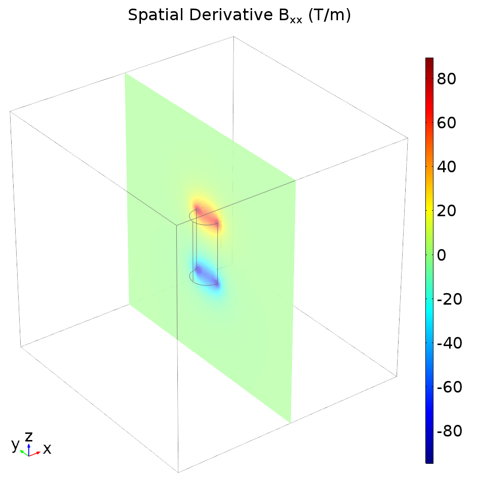
We need to use our magnetic field results with the PDE module to get COMSOL to compute the spatial derivatives. This process is covered nicely in Marc Silva’s blog post on the COMSOL website, but the general idea is to specify an identity equation with the PDE module. Our PDE is not really a differential equation, but COMSOL will calculate the field and its spatial derivatives anyway. For instance, here is a plot of \(\frac{\partial B_x}{\partial x}\).

Modeling the Magnetic Force
The magnetic force on the particles can be specified using the partial derivatives we computed in the stationary study. You’ll need to enter the forces using whatever name you chose for the field in the PDE interface. I chose to name my field “u”, so I entered the following expression as the particle tracing force:
Fx = 3.075e-12*(u1*u1x + u2*u1y + u3*u1z)
Fy = 3.075e-12*(u1*u2x + u2*u2y + u3*u2z)
Fz = 3.075e-12*(u1*u3x + u2*u3y + u3*u3z)
The leading coefficient comes from the multiplicative scalar term in the magnetic bead force equation. I obtained the parameters for this term from the magnetic bead datasheet using the same method as [1].
Modeling the Particle Trajectories
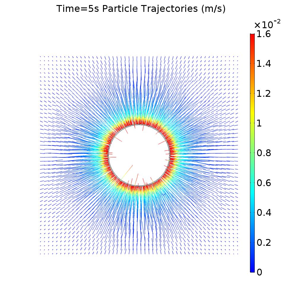
To see the particle trajectories, we can release particles in a grid formation in a plane above the magnet. I released the particles 800 μm above the magnet, since the bottom layer of our microfluidic chips has a thickness of 750 μm. The particles should be drawn toward the edge of the magnet, while the particles above the center of the magnet should only move downward. I also set a “freeze” wall condition on the magnet boundary surfaces.
The following plot shows the particle trajectories and the particle velocity for a time-dependent simulation of 5 seconds.

There seem to be a few erratic trajectories, but the majority of the particles moved in a way consistent with what I have qualitatively observed in the lab.
Conclusion
This was not an ideal quantitative simulation. To prove the validity of our simulated results, I would ideally measure the magnetic fields and observe particle speeds and trajectories, potentially using video under a microscope. This is unfortunately not possible with the equipment I currently have at my disposal.
There were a few caveats, but I was also very happy with COMSOL. There were some minor convergence issues, until I properly separated the particle tracing and magnetic field simulations into two separate studies. Once I used the stationary study as the initial condition for the time-dependent study, COMSOL smoothly converged to a solution. We could have obtained smoother partial derivatives and trajectories by simulating with a finer mesh and having a smaller time step. It would be nice if there were a way to get the PDE module to directly compute the force - this might also improve the results.
Even still, I am happy with this simulation. Although the simulation could certainly do with some improvement, the qualitative results showed exactly the kind of behavior we see in the lab. The particles tend to aggregate at the edge of the magnet, and the forces are strongest at the magnetic fringe field. This simulation also provides a good starting point for a microfluidic multiphysics simulation, where we model our microfluidic chip geometry and fluid phase interactions.
References
[1] S. S. Shevkoplyas, A. C. Siegel, R. M. Westervelt, M. G. Prentiss and G. M. Whitesides, “The force acting on a superparamagnetic bead due to an applied magnetic field,” Lab on a Chip, vol. 7, pp. 1294-1302, 2007.
[2] S. Sharma, V. K. Katiyar and U. Singh, “Mathematical modelling for trajectories of magnetic nanoparticles in a blood vessel under magnetic field,” Journal of Magnetism and Magnetic Materials, vol. 379, pp. 102-107, 2015.
[3] Q. Cao, X. Han and L. Li, “Numerical analysis of magnetic nanoparticle transport in microfluidic systems under the influence of permanent magnets,” Journal of Physics D: Applied Physics, vol. 45, p. 465001, 2012.
[4] S. Y. Zhou, J. Tan, J. Xu, J. Yang and Y. Liu, “Computational modeling of magnetic nanoparticle targeting to stent surface under high gradient field,” Computational mechanics, vol. 53, pp. 403-412, 2014.